GOMACO World Index --- GOMACO World 37.1 - June 2009
GOMACO Versatility Showcased on I-64 Project
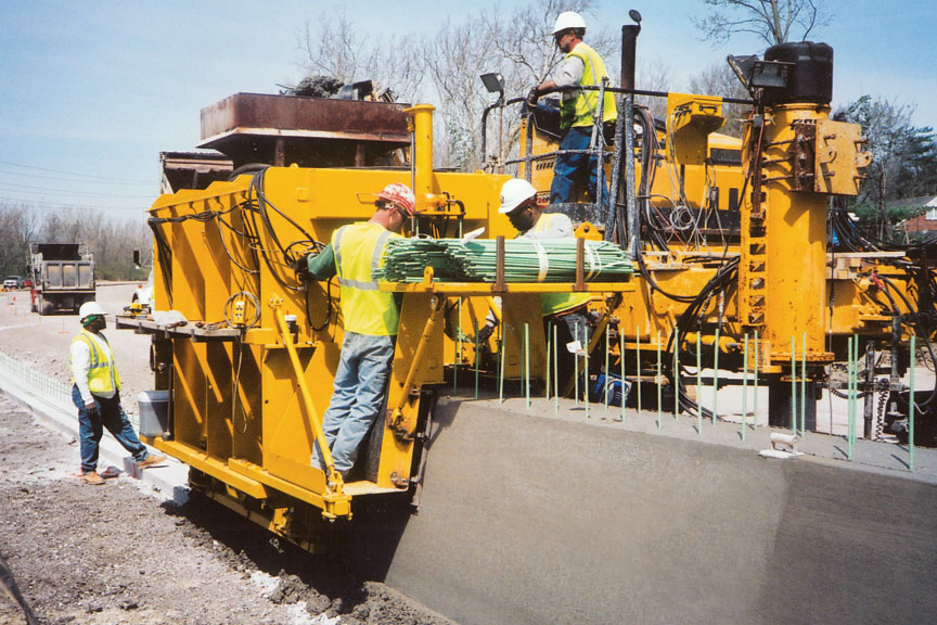
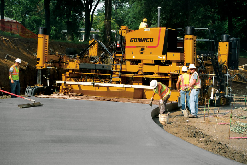
A GOMACO 9500 feeds concrete onto the belt of a four-track Commander III slipforming barrier wall on a project in St. Louis.
One of the most unique projects in Missouri history is currently in its second phase on Interstate 64 through St. Louis. The design-build project, the city’s first, is a complete replacement of approximately 10 miles (16 km) of the interstate right through the heart of the city. One-half of the 10 miles (16 km) is completely shut down to traffic while work takes place. The unprecedented move is taking years off the completion date and creating a safer environment for the construction workers.
The project is being built by a consortium called Gateway Contractors, which involves contractors Granite Construction; Fred Weber, Inc.; and Millstone Bangert, Inc. The two-year project involves 200,000 cubic yards (152,912 m3) of concrete. All of the concrete will be slipformed by GOMACO equipment.
Fred Weber and Millstone Bangert have brought their fleet of GOMACO equipment onto the project. That fleet includes three 9500 trimmer/placers, an RTP-500 placer, four Commander III four-tracks, and a GHP-2800 paver. It’s a lot of equipment, but the variety of applications the equipment is slipforming is astounding.
The Commander IIIs are slipforming shoulders, medians, variable-width ramps, inside median barrier wall, outside barrier wall, retaining wall, roundabouts, bridge parapet, truck lanes, half-shaped barrier wall against MSE (mechanically-stabilized earth) wall, and moment slabs for the sound wall. That’s over 10 different applications that one machine is capable of slipforming.
“In my opinion, the Commander III is the best machine around and you can’t beat it for versatility,” Jim Jackson, Operations Manager of Paving for Fred Weber, said. “That machine will do anything you ask it to do. It’s just amazing what it can do, as small as it is.”
Paving the Mainline –
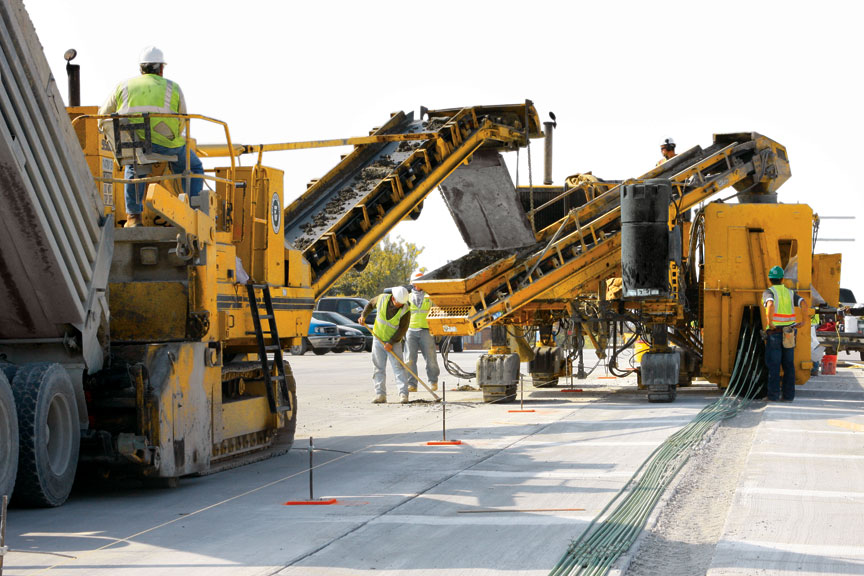
But let’s start at the beginning of the project and the removal of the existing roadway. All of the material on the project was recycled. The concrete was crushed and used again for the base material. The base for the I-64 project consists of 10 inches (254 mm) of six inch (152 mm) minus rock, capped with two inches (51 mm) of Type 5 rock. The top layer is trimmed to the accurate, final grade with a GOMACO 9500 with an 18 foot wide (5.5 m) trimmerhead.
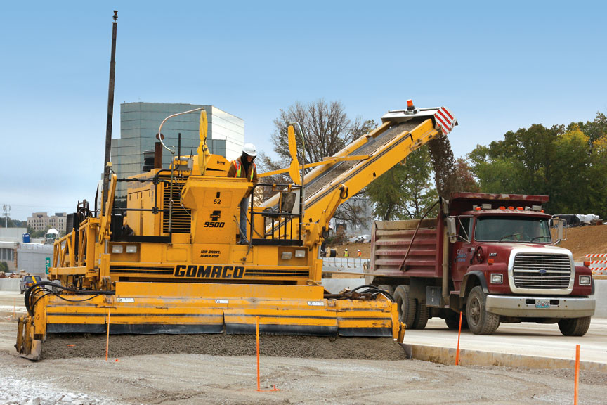
Millstone Bangert is responsible for all of the mainline paving on the project and are using their GOMACO four-track GHP-2800 paver. Project smoothness specifications require a reading of under 30 and Millstone Bangert is consistently running between 10 and 12 on the zero-blanking band. Smoothness, according to Ron Dibler, Millstone Bangert’s Paving Superintendent, begins with the base.
“Good ride is a process that begins from the ground up,” Dibler said. “You have to have good string, consistent mix and try to keep the paver moving with minimum stops. Most important though, is a good solid trimmed base to pave on and run the paver’s tracks.”
Each paving pass with the GHP-2800 is nine or 10 inches (229 to 254 mm) thick and 25 feet (7.6 m) wide. They’re building four new lanes of interstate, for both the eastbound and westbound sides. Paving production averages between 2500 to 3000 cubic yards (1911 to 2294 m3) per day.
All of the concrete for the project is being supplied by two on-site batch plants. Concrete is delivered to the paving site by tandem-axle dump trucks. The concrete is a Missouri Department of Transportation (MDOT) approved mix with an average slump of 1.5 inches (38 mm).
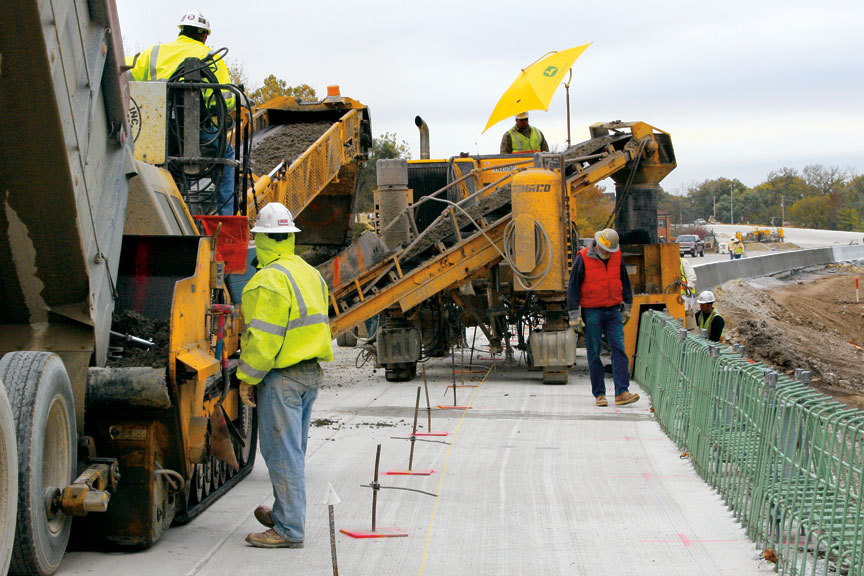
A 9500 trims grade for the mainline portion of the paving project. The trimmer is equipped with an 18 foot (5.5 m) wide trimmerhead.
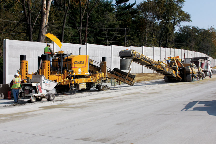
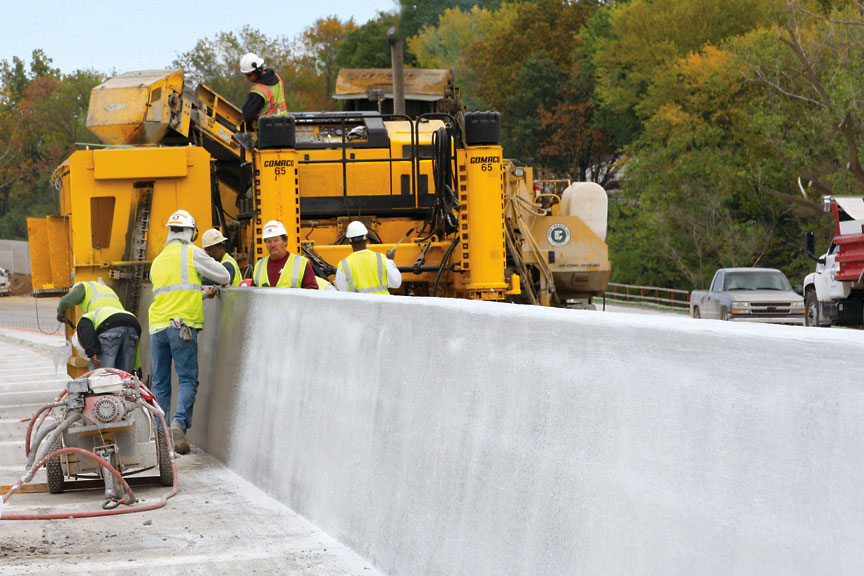
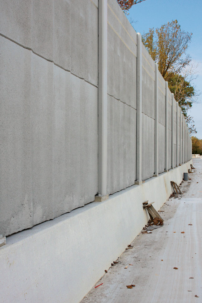
The Commander III slipforms barrier next to a section of already finished sound wall.
All of the Wall –
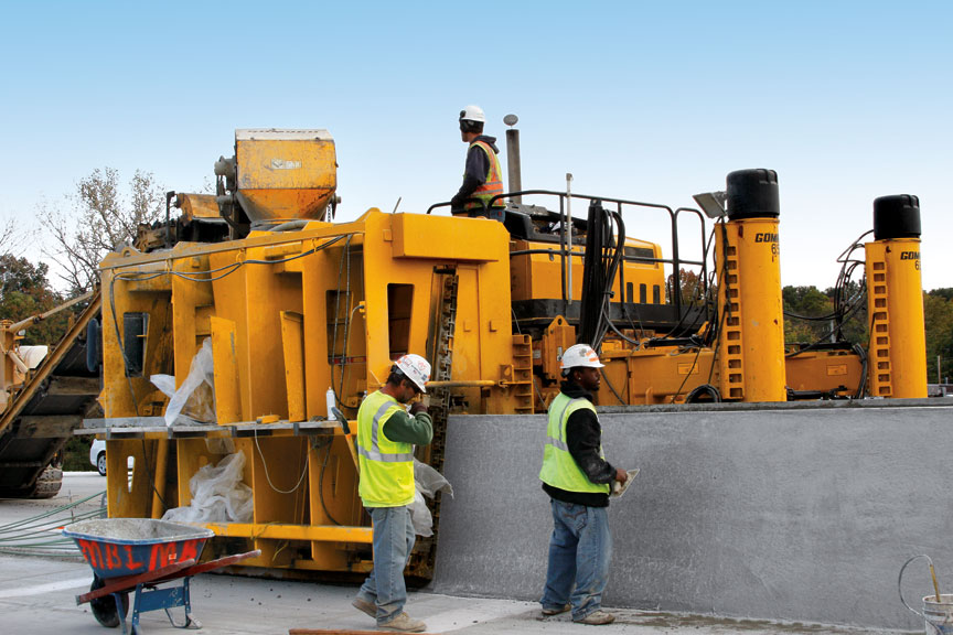
Slipping the Outside Barrier Wall – The profiles for the inside and outside barrier walls are very similar, but the outside barrier has sound wall mounted to the top of it. A Commander III is used to slipform a moment slab with a rebar grid. The steel for the wall is tied to the rebar grid in the moment slab. With the steel in place, the spacing for the sound wall is meticulously plotted and the anchoring bolts for each post are carefully set.
“The sound wall posts have to be put in the exact location, because each panel is made to fit a certain area,” Dibler said. “After the cages are built, we dry run the steel to make sure everything is going to work and it’s all set to the right height.”
The concrete trucks dump their loads into an RTP-500, which then feeds the belt on the Commander III. The central mix concrete, according to Dibler, gives their concrete more consistency and allows them to run a drier mix for their barrier work.
Behind the Commander III, workers have to locate the anchoring bolts for the sound wall, dig them out and expose them so the posts can be installed after the concrete has cured.
Center Median Barrier – A 9500 placer feeds another four-track Commander III as it slipforms the variable-height center median barrier. The height of the wall varies from four feet (1.2 m) to 7.25 feet (2.2 m).
The non-variable height barrier has 10 longitudinal bars fed into the front of the mold for wall reinforcement. The variable-height barrier is slipformed over a steel cage in the lower half of the wall. They are inserting six longitudinal bars into the front of the mold for the top section of the wall.
Retaining Wall – The consortium engineered a cost-saving measure on the project by stacking two slipformed walls on top of each other instead of putting in MSE wall. The first retaining wall varies in height between three feet (0.9 m) and six feet (1.8 m). Two rebars are hydraulically inserted vertically into the 24 inch (610 mm) wide top of the wall and vibration is applied to the rebar during insertion. The wall is allowed to cure, and then backfilled. The roadway is brought up to grade, and then another section of wall is slipformed on top of the existing wall.
“The slipformed retaining wall replaces MSE walls shorter than nine feet (2.7 m) in areas that would retain dirt,” Dibler explained. “Rather than building a costly MSE wall, we were able to slipform retaining walls.”
Ten longitudinal bars are fed into the front of the mold on the Commander III for the non-variable barrier wall.
Two rebars at a time are hydraulically inserted into the top of this barrier. Another wall will be slipformed on top to form a retaining wall on the project.
Side-mounted Shoulder and Medians –
All of the shoulder and medians on the project are slipformed with a side-mounted mold on the Commander III. Medians are slipformed six feet (1.8 m) wide. Shoulders vary from four to 10 feet (1.2 to 3 m), or 8.5 feet (2.6 m) if there is a barrier wall on it. Zero-clearance paving against the MSE wall was accomplished after modifying their mold.
“We had an idea of moving the sideform cylinders and mounting structure from the outside of the mold to the inside of the mold and minimizing the thickness of the sideform,” Dibler said. “We were able to get that down to about two inches (51 mm), which allows us to slipform closer to the walls, and that’s been a big help on this job.”
The Commander III is equipped with a variable-height mold for slipforming both the variable and non-variable center median barrier.
The first step to the sound wall is slipforming a moment slab. The slab features extra steel reinforcing slipformed into the concrete.
Variable-width ramps with the V2 mold –
Two of the Commander IIIs on the project are equipped with V2 variable-width molds. The V2s have the optional auto-width adjustment package to allow the mold to make on-the-go width changes and produce a tapered slab. A second stringline is set to follow the desired tapered slab, and sensors on the paver use that second stringline to control the cylinders that extend or retract the frame and side-shift the mold. The operator simply puts the system on automatic when approaching the width transition and the mold adjusts to the new paving width automatically.
Width changes on the ramps include transitions from 15 feet (4.6 m) down to 12 feet (3.7 m) wide, and 18 feet (5.5 m) down to 12 feet (3.7 m) wide. The transitions are made on-the-go, with no need to stop and adjust the paver width.
“This is something I’ve been looking forward to for a long time,” Jackson said. “We’ve always had to stop paving and add or take out a section, and that takes time. Then, when we first got our V2 mold, we had to set our stringline like normal and paint a line where we wanted our transition. A worker would stand there with the remote in hand and try to follow that line manually.
“Now with this new package and the extra cylinder and stroke, we can set our second stringline and the transitions follow the stringline. You don’t have to worry about anything else. It gives us such flexibility and different options. It’s just a very smooth transition.”
It allows them to pave at different widths, with one machine, all in the same day. On a project like this, it’s a necessity and a huge time savings.
“We’ve been able to slipform variable pavement widths very easily, and that’s been a big help on this project,” Dibler said. “The new roller frame on the Commander III and the transition sensors go right through the width changes without a problem.”
The V2 mold is making on-the-go width changes from 15 feet (4.6 m) down to 12 feet (3.7 m), and 18 feet (5.5 m) down to 12 feet (3.7 m).
A roundabout on the project was slipformed 20 feet (6.1 m) wide with integral curb around a 45 foot (13.7 m) radius.
Roundabouts –
Another cost-saving measure on the project included building two roundabouts instead of entrance and exit ramps. The 20 foot (6.1 m) wide, eight inch (203 mm) thick roundabouts, with integral curb on one side, had to be built around a 45 foot (13.7 m) radius. Fred Weber decided to pave the first roundabout in two separate pours. The first was 10 feet (3 m) wide and the second was the same width with a three inch (76 mm) mountable curb.
“The tight radius intimidated us a bit on the first roundabout,” Jackson said. “The second one though, we decided to pour the full 20 foot (6.1 m) with the curb on it. It worked out just fine, and we accomplished it all in one pour, instead of two.”
To finish out the roundabout, a lane was slipformed inside of its radius. The lane, which is used to assist trucks through the roundabout, was nine inches (229 mm) thick, and 10 feet (3 m) wide with a six inch (152 mm) vertical curb.
The I-64 project is scheduled to have traffic back on the finished second phase by the end of this year. It’s a deadline the consortium is confident they’ll make.
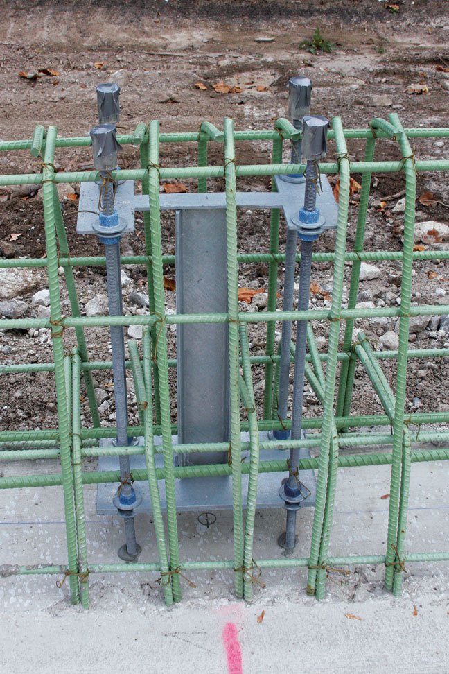
The steel caging for the barrier wall is anchored to the steel in the slab. Extra supports for the sound wall are incorporated into the wall’s steel cage. The posts that support and hold the sound wall panels are then bolted to the supports after the concrete wall has cured.
Subscribe to Receive GOMACO World Magazine