GOMACO World Index --- GOMACO World 32.1 - February 2004
Accuracy and Versatility of the GOMACO Trimmers
By Dennis Clausen, GOMACO University Director of Training
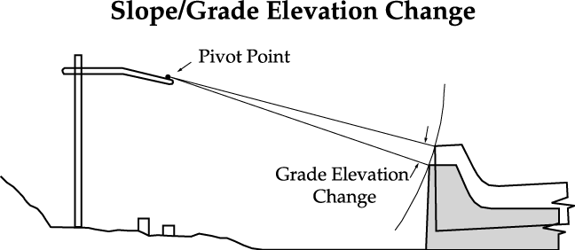
Have you ever wondered why the elevation of your product changes when you change the cross fall (slope)? It's because automated slipform pavers and trimmers pivot around the stringline. The stringline acts as a pivot point when cross slope is changed. As slope is increased or decreased, grade elevation is affected. The amount of elevation change is in relation to the offset and the percent of slope change. At those locations where slope changes are required, it is recommended that the stringline height be changed to compensate. When the stringline is on the left side of the machine and the amount of slope is increased, the stringline should be lowered, and the line should be raised as the amount of slope is decreased. When the stringline is set under the machine and the slope is increased, the line must be raised, and must be lowered when the slope is decreased. (See Diagram 1)
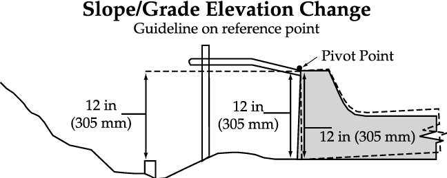
If the stringline guide is positioned even with and at the same elevation as the top back of curb (reference point), there will be no change in the vertical elevation of the curb when the cross slope of the machine is changed. Assume the stringline is positioned 12 in. (305 mm) above the top of the grade hub and the curb is positioned even with (no offset) the stringline. With 0.0% of slope, the top of the curb is positioned 12 in. (305 mm) above the grade hub. If the slope is changed to 2.0%, there will be no elevation change and the measurements will remain the same. Note: Positioning the stringline directly over the reference point is impossible in most cases as the trimmerhead, slipform mold hopper and various other protrusions are in the way. Also, with the stringline over the reference point, it would be very difficult for the finishers to do any repair to the product. (See Diagram 2)
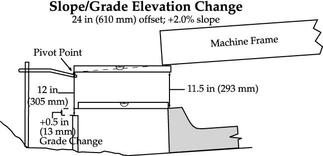
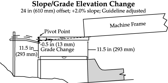
In this example, the slope of the machine was changed to +2.0% (right side higher than left). As the elevation of the right side increases, the machine pivots around the stringline (grade sensor(s) must remain electrically centered). With a 24 in. (610 mm) offset, the elevation of the curb will increase a proportional amount. To determine the elevation change, multiply the offset by the amount of slope change. In this example, multiply 24 in. (610 mm) (offset) by +2.0% (slope change). Therefore, 24 in. (610 mm) x +0.02 (decimal equivalent) = +0.5 in. (13 mm) of grade change on the product. The top of the curb would be +0.5 in. (13 mm) above the top of the grade hub. The measurement between the stringline and the top of the curb would be 11.5 in. (293 mm). The finished product would therefore be 0.5 in. (13 mm) too high. (See Diagram 3)
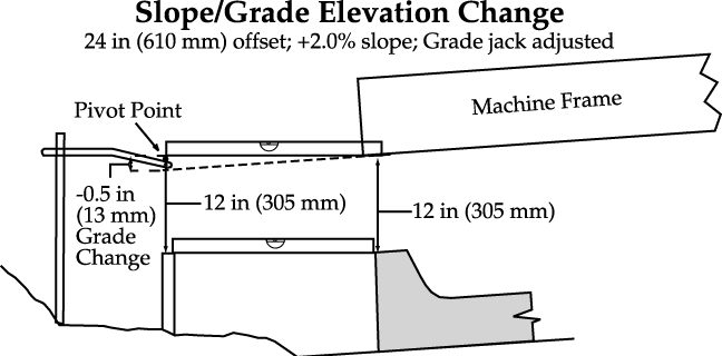
When the slope of the machine is changed to +2.0% with a 24 in. (610 mm) offset, the increase in elevation on the right side will cause the elevation of the curb to increase +0.5 in. (13 mm). To compensate for the increase in elevation, the curb must be lowered. One method used to change the elevation of the curb is to adjust the grade jack(s) (one turn = 0.12 in. (3 mm)). When making a transition from 0.0% slope to +2.0%, the grade jack(s) should be adjusted evenly over the entire transition distance. For example, if the transition distance is 100 ft. (30 m), the grade jack(s) should be adjusted one turn every 25 ft. (7.6 m). The measurement between the stringline and the hub will remain at 12 in. (305 mm) and the top of the curb will be even with the top of the grade hub. The measurement between the stringline and the top of the curb will remain 12 in. (305 mm). The bottom of the machine frame will be 0.5 in. (13 mm) lower. Note: This method of grade adjustment is not normally recommended as it relies on multiple people attempting to make the correct adjustments at the correct intervals. It also increases the chance of errors if the grade must be pre-trimmed prior to pouring. (See Diagram 4)
The best method used to change the elevation of the curb is to adjust the stringline. To determine the amount of stringline adjustment at each station (stringline holder), divide the transition distance by the number of stations in the transition. For example, if the transition distance is 100 ft. (30 m), and there are four stations, the stringline should be adjusted in 0.12 in. (3 mm) increments every 25 ft. (7.6 m). The line would be adjusted to the correct measurement at the beginning of the transition. At the first station, the line would be adjusted 0.12 in. (3 mm), adjusted 0.24 in. (6 mm) at the second station, 0.36 in. (9 mm) at the third station, etc. until adjusted the total amount. The distance between the stringline and the grade hub will be decreased by 0.5 to 11.5 in. (13 to 293 mm). The distance between the stringline and the top of the curb will also be decreased by 0.5 to 11.5 in. (13 to 293 mm). The top of the curb will be even with the grade hub. (See Diagram 5)
Subscribe to Receive GOMACO World Magazine
