GOMACO World Index --- GOMACO World 34.1 - February 2006
GOMACO University: Tips For Setting Up And Paving With 3D Stringless Controls
By Dennis Clausen, GOMACO University Director of Training
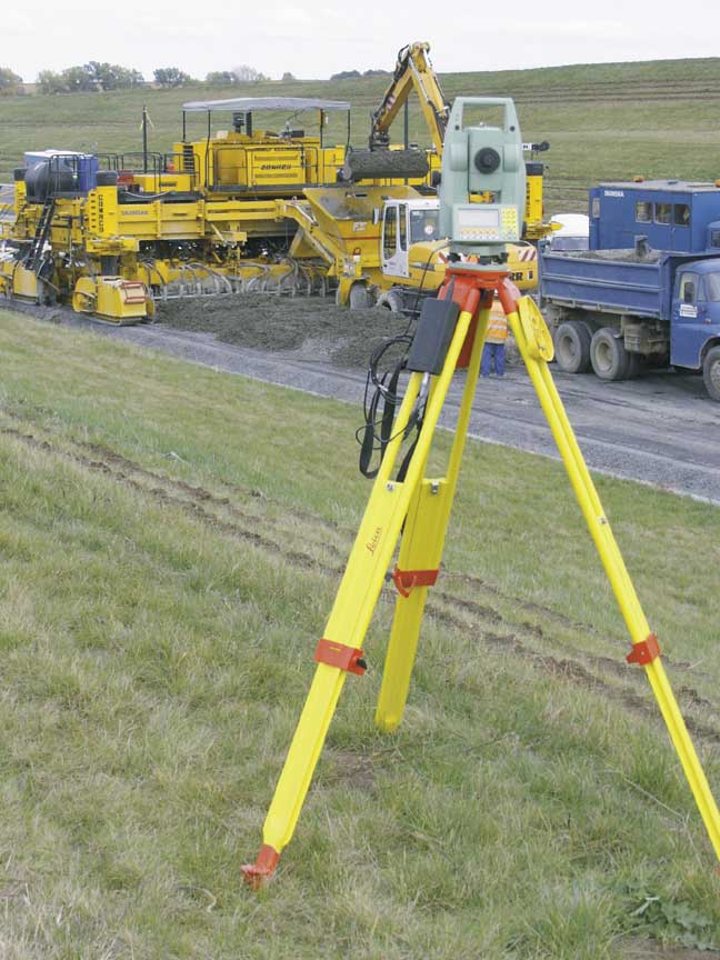
A Leica total station tracks the progress of the GOMACO GP-4000 paver on a highway project in the Czech Republic.
How many times during paving operations has your stringline broken, or you have had to take it down to allow trucks or other equipment to pass? How accurate is your stringline? How much does it cost to set the stringline and constantly monitor it? Have you ever wondered if there was an easier way to control your paver rather than setting stringline?
There is a better way. It’s through the use of the Leica stringless control system. The system controls the paver through the use of laser beams and radio signals.
When surveyors plot a project, they often do it using a total station and a measurement prism. After they have established reference points on the project, the information is inserted into a design program and the final project is developed, including horizontal and vertical alignments. Now, instead of using this information to place stakes on the job, the information can be loaded into the Leica computer and then used to control the machine.
For machine setup, the Leica MPC4 machine controller is mounted on the GOMACO machine. Power is supplied to the controller from the machine electrical system. The CAN-Bus cable between the G21 controller and the switch box on the machine is replaced with a “Y” CAN cable which allows the controller to be connected into the machine control system. Two prism mounting poles are attached to the machine with a 360 degree prism attached to the top of each one. One pole is attached to the left rear of the machine and the other is attached to the right rear. A “dual axis” slope sensor which measures cross slope (side to side) and long slope (front to rear) is mounted to each of the prism poles and connected to the Leica controller. The prisms basically locate the elevation of the rear of the machine, while the dual axis sensors control the front elevation.
After all of the hardware is mounted on the machine, it will be necessary to calibrate the system. To calibrate the system, it will be necessary to establish the paving pan coordinates. A total station is used, along with a measuring prism to measure four points on the bottom of the paving pan, one at each corner. The first step is to enter the width and length of the paving form into the controller. Once the mold information is entered, an elevation measurement is “shot” for the front and rear of the bottom side of the paving form on each side. This information is automatically stored in the controller. The next step is to “shoot” each of the 360 degree prisms. This allows the system to calculate the distance from the paving pan to the prisms in a very accurate manner. The system now knows where the paving pan is in relation to the prisms as the machine moves about the project. After these measurements are recorded, it will not be necessary to retake them unless the width of the paving form changes or the location of the prisms is changed.
Once the measurements are all stored in the controller, it is time to set the machine up on the job site. The machine is moved to a location that is relatively close to the proper paving position. The total stations (one for the left and one for the right) are positioned in a location that will be clear of all construction traffic. It is also suggested to have them set on an elevation that is high enough to allow the laser tracking beam to be above all construction traffic. Once the total stations are positioned, they are then used to locate at least three reference locations on the job site. After each total station “knows” its location on the job site, one is targeted at the prism on the left side of the machine and the other one is targeted at the right prism. As the paving operation commences, it is possible to make adjustments to the elevation and alignment by simply changing the vertical or horizontal offsets in the computer.
Normally during paving operations, three total stations are used. The paver only requires two for control. The third can be used to check the slab elevation, or it can also be used for “leap frogging” the stations.
For example, the station controlling the left side of the paver may be set 250 feet (76 m) from the machine and the one controlling the right side may be 500 feet (152 m) from the machine. When the machine begins to get out of range of the left total station, that side can be switched to the third total station. The total station that is not being used can then be moved to a new position to take over control of the right side of the machine when it gets out of range of the station controlling it. That station is then moved forward to control the left side when it again gets out of range. This procedure continues until the project is completed.
With the Leica system, several different projects can be “loaded” into the controller and the corresponding one selected as necessary. This allows moving from one location to another without the need to stop to download the required program. No more stringline in the way!
GOMACO University: Registrations are now being accepted for all of the 2006 GOMACO University classes. Contact Shari Simmons at GOMACO University to register at 1-800-831-2320, or visit the University’s website at http://www.gomaco.com/university to view the list of classes available or to register online.
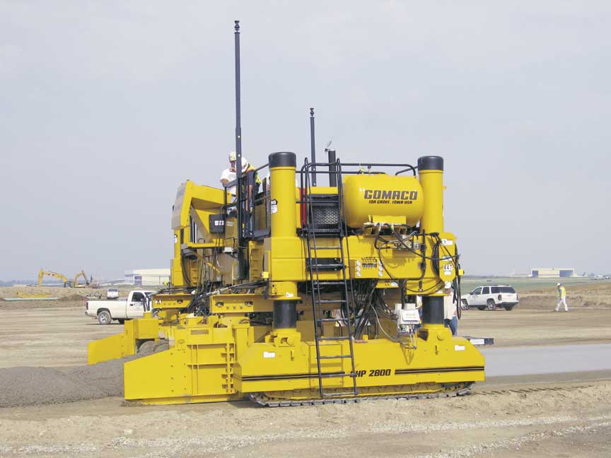
A GHP-2800 paver slipforms an econocrete subbase on this project at the Indianapolis International Airport.
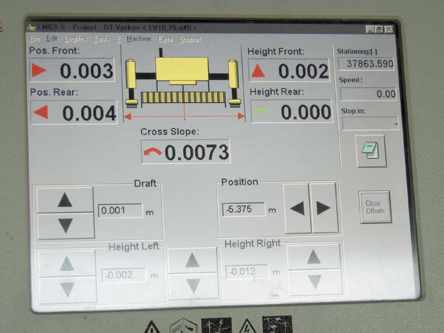
The Leica MPC4 computer is mounted on the GOMACO machine and supplies the operator with system information.
It’s necessary to establish the paving pan coordinates to calibrate the system and this drawing illustrates that technique
Subscribe to Receive GOMACO World Magazine