GOMACO World Index --- GOMACO World 37.2 - September 2009
Slipforming Eases a Complicated Project
Extrudakerb slipforms a unique profile of barrier wall in Belfast, Northern Ireland.
Slipforming was the easy part of this project. It was the logistics, engineering time, mold profile development, and numerous other factors that were almost overwhelming. Extrudakerb, a contractor based out of Doncaster, England, recently completed a project that was 12 months in the planning phase. It involved the engineering of a new concrete barrier system capable of accommodating up to 1.2 meters (3.9 ft) of roadway level differences.
The project was on Junction 3 to 4 of the M2 expressway in Belfast, Northern Ireland. Extrudakerb, along with their Irish partner, Highway Barrier Solutions, won the contract to design and build a central reserve concrete barrier, retaining wall and concrete drainage system.
“It was one of the most complex jobs that we’ve ever had,” James Charlesworth, Director of Extrudakerb, said. “We originally planned for the entire project to take four months to complete, but thanks to some superior planning and organization, we finished four weeks early.”
The project required Extrudakerb to set up a local office in Belfast. They transported eight truck loads of equipment, including a four-track Commander III and seven paving molds, across the Irish Sea. Extrudakerb even purchased mini-busses to transport their workers between England and Belfast. The crews worked two full weeks and then had one long weekend off.
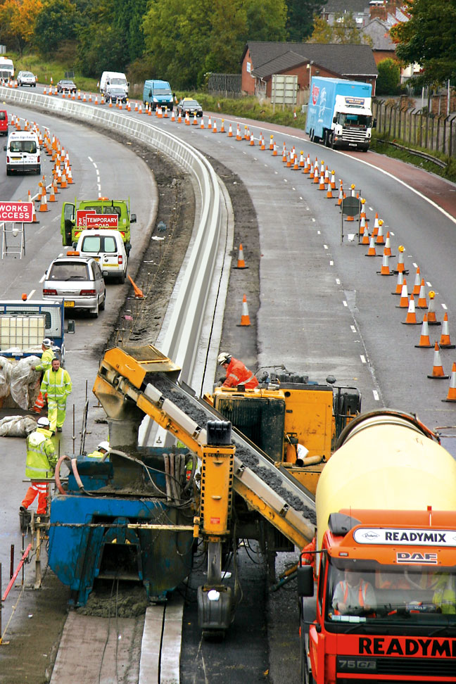
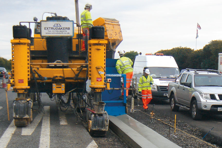
The Commander III four-track was set up to pour on the right side, so ready-mix trucks could travel with the flow of traffic. It eliminated the need for the trucks to turn around in the confined space of the site.
The first slipforming steps on the project involved the drainage system. Extrudakerb slipformed either a v-channel or a 300 millimeter (11.8 in) diameter slot drain with their Commander III. Approximately 4500 meters (14,764 ft) of concrete drainage system was slipformed.
The concrete barrier system and retaining wall was next. It was, by far, the most complicated aspect of the project, and required some unique engineering solutions.
“We developed a concrete barrier system and retaining wall to accommodate carriageway level differences of up to 1.2 meters (3.9 feet),” Charlesworth said. “The concrete structure needed to meet the structural requirements of a carriageway retaining wall and that of the foundation for a Britpave concrete barrier system.
“The overall width should not exceed one meter (3.3 ft), and a standard barrier has a footprint of 542 millimeters (21.3 in). However, street lighting had to be sited within that central reserve, and that’s where the challenge was.”
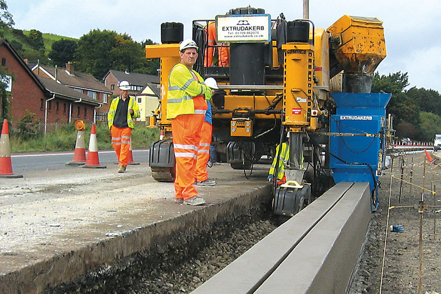
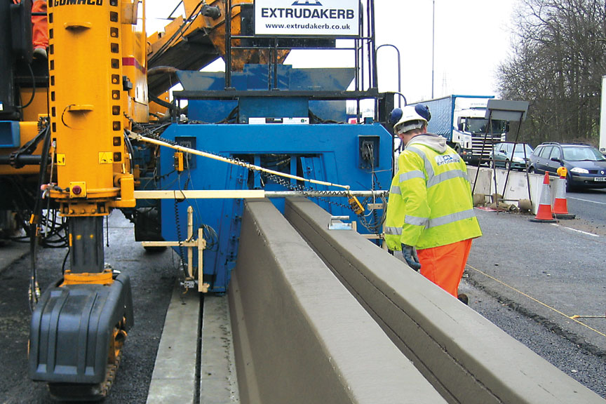
When roadway differences were less than 300 millimeters (11.8 in), Extrudakerb slipformed a wide concrete step barrier with a trough for the cable. The wide barrier had a 942 mm (37.1 in) base, a top cap that was 600 millimeters (23.6 in) wide, and was 900 millimeters (35.4 in) tall. Steel reinforcing cable was inserted into the front of the mold at 300 millimeters (11.8 in) and 450 millimeters (17.7 in) from the top of the wall.
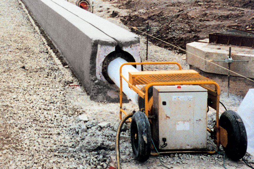
The slot drain had a diameter of 300 millimeters (11.8 in) and was slipformed over a plastic, inflated tube.
Concrete was supplied by local producer, Cemex, and was delivered to the site by ready mix-trucks carrying six and eight cubic meter (7.8 and 10.5 yd3) loads. The mix was a grade C35 with air entrainment and polypropylene fibers that complied with Britpave specifications. Slump averaged 20 millimeters (0.8 in).
When roadway levels exceeded 300 millimeters (11.8 in), Extrudakerb would first slipform a single-sided step barrier with a 499 millimeter (19.6 in) base, 200 millimeter (7.9 in) wide top cap, and 900 millimeters (35.4 in) tall. A concrete in-fill was placed between the new wall and the existing roadway to accommodate the height difference before the second wall could be slipformed.
The second wall was standard Britpave step barrier with a 542 millimeter (21.3 in) wide base, 200 millimeter (7.9 in) wide top cap and 900 millimeters (35.4 in) tall. It had steel reinforcing fed into the mold 150 millimeters (5.9 in) and 300 millimeters (11.8 in) from the top of the wall.
Extrudakerb slipformed the wide step barrier when the differences in roadway heights was less than 300 millimeters (11.8 in).
The first step of the project required slipforming a drainage system, with either a v-channel or slot drain.
“Production averaged around 20 cubic meters (26.2 yd3) per hour on the wide step barrier,” Stewart Cousins, Technical Manager for Extrudakerb, said. “Outputs peaked at 25 cubic meters (32.7 yd3) per hour and with that, we exceeded our previous daily production records.”
A large amount of hand-forming work was required on the project as well as slipforming. Extrudakerb manufactured their own steel formwork to create transitions between the twin barrier to the wide barrier. Formwork transitions were also needed between the walls and the concrete bridge piers and sign gantry bases.
“The formwork dictated the project because it took longer than the machine slipforming,” Cousins said. “It all had to be carefully coordinated so there were no big delays waiting on formwork to be released at the end of the project.”
The wide step barrier required 0.7 cubic meters (0.9 yd3) of concrete to slipform just one meter (3.3 ft). The sheer size and dimensions of the wall are illustrated in the drawing.
The complicated sequence of the project is best shown in this illustration.
Another major concern was creating light column buildouts for street lights. Gaps were left in the second barrier wall for light column locations. Pre-fabricated reinforcement cages and anchoring bolts were installed in those gaps. The area between the two barrier walls was filled with concrete. Then, prefabricated formwork was placed and used to construct the column and build-out to hold the street light.
In total, over 8000 cubic meters (10,464 yd3) of concrete was used to complete the barrier on Junction 3 to 4. Extrudakerb completed all of the work in just three months, four weeks ahead of their planned completion schedule.
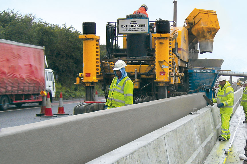
Extrudakerb poured off the right-side with their four-track Commander III on all of the different profiles on the project.
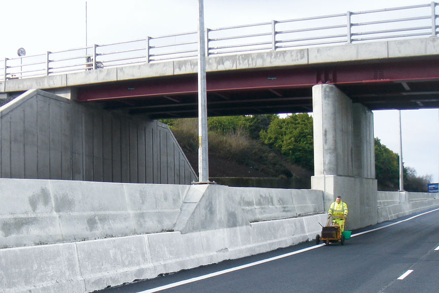
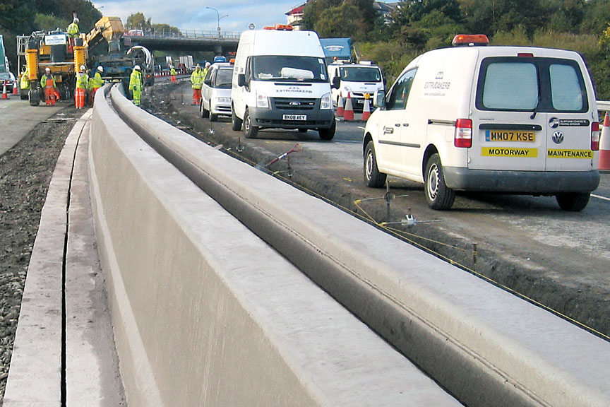
The finished wall shows the hand-formed concrete support for the street lamps and bridge pier approaches.
Drawings illustrate the two types of Britpave step barrier used to slipform the areas where the roadway height exceeded 300 millimeters (11.8 in).
Subscribe to Receive GOMACO World Magazine