GOMACO World Index --- GOMACO World 28.2 - August 2000
University Forum: Dennis' Barrier Tips
When pouring barrier or parapet wall, there are several items that must be taken into account to achieve a successful pour.
First and foremost, the machine must be of adequate size and power to handle the type and size of barrier being poured. If the wall is a standard 32 inch (813 mm) Jersey-style wall, this can be handled with any of the curb and gutter machines with the proper attachments (Commander III, GT-3600, GT-3300, Commander II, GT-3200, or GT-6000). However, when it comes to walls up to 42 inches (1067 mm), or walls that are wider than normal, these should be handled by the GT-3300, GT-3600 or the Commander III. For walls that are taller than 42 inches (1067 mm), or variable walls the Commander III is recommended.
The slipform mold must be clean. If concrete build-up is present on the inside of the mold, it will cause the concrete to pull and possibly tear. If concrete build-up is present in the corners of the hopper, the concrete flow into the mold will be restricted, causing slow production rates and problems filling the top of the wall.
The width of the slipform mold must be constant front to rear. If the rear of the slipform mold is considerably narrower (squeezed) than the front, it will cause the concrete to pull and tear. When measuring the width of the bottom of a parapet mold, keep in mind that normal GOMACO specs call for a batter of approximately 0.5 inches (13 mm) per vertical 12 inches (305 mm), for example, a 32 inch (813 mm) mold would be an extra 1.3 inches (33 mm) wider than specified. For molds over 42 inches (1067 mm) without cage steel, this amount is increased to .75 inches (19 mm) per vertical 12 inches (305 mm). Note: If pouring over cage steel with a parapet form, the batter can be eliminated by written request.
When setting the machine to final grade, the measurement for the height should be .75 inches (19 mm) higher than the finished wall to allow for concrete slump. When pouring barrier or parapet wall, consistent concrete slump is a must. Recommended concrete slump is .75 inches (19 mm) ± .25 inches (6 mm). If the concrete slump varies more than .25 inches (6 mm), the top line will appear to move up and down, giving the appearance that the machine is not holding grade. It is also recommended to use crushed aggregate versus plain river rock. The round spherical shape of the river rock may cause a tendency for the mix to slide. Crushed aggregate will have an interlocking effect, helping to hold the mix together.
Installation of vibrators in a barrier or parapet mold is critical to a well-consolidated wall. The vibrators are normally installed in the horizontal (underslung) position with the tip angled downward slightly. The lower vibrator(s) is normally positioned about six inches (152 mm) up from the base. An additional vibrator is normally positioned in the center of the wall and one is positioned at the top of the wall. Occasionally a vibrator is placed crossways in the front of the form to help with concrete flow (Figure 1).
When pouring over cage steel, it is important to keep the vibrators at least one inch (25 mm) away from the steel. If a vibrator should touch the steel, it can cause the top of the wall to slump down and steel marks to appear in the surface of the wall (Figure 2).
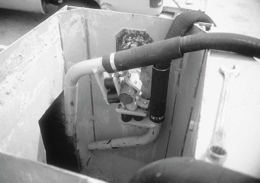
Figure 1
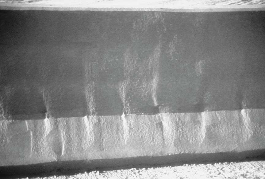
Figure 2
It is also important to dry run (without concrete) the length of the pour if pouring over cage steel. Make certain that the steel is properly centered in the form and that no vibrator is touching any part of the cage (Figure 3).
A final item that is of utmost importance is the setting of the stringline guide. When pouring normal barrier, the line can be set to the left of the machine, the same as for curb and gutter. When pouring parapet on a bridge deck, it is often necessary to set the line under the machine. The line is normally set eight to nine inches (203 to 229 mm) above the bridge deck and five feet (1.52 m) from the front face. Line supports can be made by welding a 12 inch (305 mm) piece of .75 inches (19 mm) round stock to a 12 inch (305 mm) square plate. After the line has been properly set, sight along it to check for deviations that must be adjusted. Once the line is set, it is recommended to draw a chalk line around the support plates so that if the line is accidentally moved, it can quickly be returned to the original spot (Figure 4).
Following these tips will provide you with a starting point to achieve quality barrier. As with all instructions and tips, these are only recommendations and whatever tricks you use should produce excellent wall.
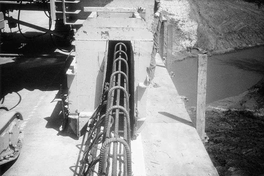
Figure 3
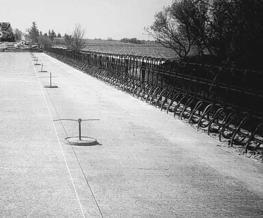
Figure 4
Subscribe to Receive GOMACO World Magazine